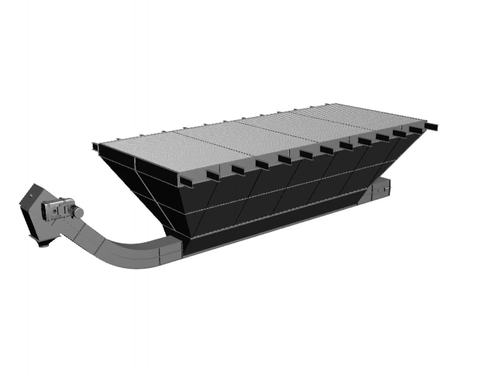
Змішувач горизонтальний скребково-лезовий періодичної дії марки ЗСЛ-400 призначений для змішування компонентів комбікормів після порційного дозування. Змішувач може бути застосований на комбікормових заводах і в цехах по виробництву збагачувальних сумішей.
Передбачено виконання змішувача Н-ЗСЛ-400, (деталі якого, що контактують з продуктами змішування, виконані з нержавіючих сталей), цей змішувач призначений для змішування харчових концентратів або преміксів.
|
НАЙМЕНУВАННЯ ПАРАМЕТРА
|
ЗНАЧЕННЯ |
|
Продуктивність технічна до, кг |
200 |
|
Місткість, м.куб |
0,4 |
|
Ступінь однорідності змішування до, % |
95 |
|
Цикл змішування, хв |
3-4 |
Призначення виробу
Змішувач горизонтальний скребково-лезовий періодичної дії марки ЗСЛ-400 призначений для змішування компонентів комбікормів після порційного дозування. Змішувач може бути застосований на комбікормових заводах і в цехах по виробництву збагачувальних сумішей.
Передбачено виконання змішувача Н-ЗСЛ-400, (деталі якого, що контактують з продуктами змішування, виконані з нержавіючих сталей), цей змішувач призначений для змішування харчових концентратів або преміксів.
Ступінь крупності окремих компонентів змішування повинен знаходитися в діапазоні від 0,1 до 3,0 мм.
Основні параметри ЗСЛ-400
|
НАЙМЕНУВАННЯ ПАРАМЕТРА
|
ЗНАЧЕННЯ |
|
Продуктивність технічна до, кг |
200 |
|
Місткість, м.куб |
0,4 |
|
Ступінь однорідності змішування до, % |
95 |
|
Цикл змішування, мин
|
3-4 |
| Частота обертання ротора, об/хв |
47 +/- 3 |
| Встановлена потужність, кВт |
7,5 |
|
Час завантаження, хв |
0,45 |
|
Час вивантаження, хв |
0,45 |
|
Габаритні розміри, мм -довжина -ширина -висота |
1910 |
|
Вага, кг |
700 |
Вологість компонентів не повинна перевищувати гранично-допустимої вологості передбаченої правилами для комбікормової промисловості.
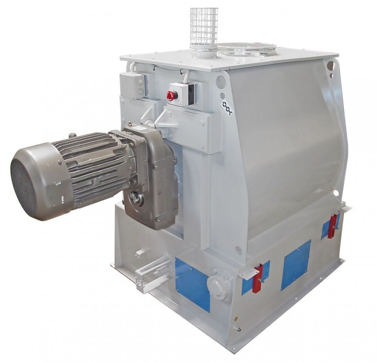
Пристрій і робота
Змішувач ЗСЛ-400 складається з:
-корпусу,
-ротора,
-привода,
-бомболюка,
-пневмопривода бомболюка,
-пристрою підпору бомболюка.
Корпус змішувача ЗСЛ-400 являє собою сталеву зварену конструкцію, напівциліндричної форми. У бічних стінках корпусу змішувача є вікна, закриті кришками, зблоковані з електродвигуном кінцевими вимикачами і призначеними для проведення ремонтних робіт, візуального контролю і періодичної очистки змішувача зсередини скребковим та пневматичним інструментом.
КАТЕГОРИЧНО ЗАБОРОНЯЄТЬСЯ відключати кінцеві вимикачі на кришках при роботі і технічному обслуговуванні змішувача, а також продовжувати експлуатацію змішувача при їх несправності.
Ротор являє собою вал, на якому розташовані 6 лопаток (скребків). Лопатки розташовані під певними кутами, що забезпечує інтенсивне перемішування завантажуваного продукту. Вал ротора спирається на підшипники, які встановлені на корпусі змішувача.
Привід забезпечує задану частоту обертання ротора від електродвигуна через редуктор.
Бомболюк вивантажувальний складається з двох стулок, загнутих по радіусу, з привареними пластинами і ребрами жорсткості. Стулки з допомогою важелів кріпляться на валах. Відкриття і закриття стулок бомболюка проводиться за допомогою пневмоциліндрів пневмопривода бомболюка, які допомогою важелів і шпонкових з'єднань провертають стулки навколо осей валів, встановлених в підшипникових вузлах, на необхідний кут повороту, який відповідає положенням: відкрито і закрито. Пристрій підпору бомболюка 6 складається із замків, розташованих на валу, які замикають бомболюк від можливого відкриття під час перемішування продукту. Замки працюють синхронно і приводяться в рух за допомогою пневмоциліндра, шток якого висунутий до упору в початковому стані, коли стулки закриті. Стулки працюють наступним чином. У вихідному положенні штоки пневмоциліндрів відсунуті до упору – стулки закриті. По команді системи управління перемикається пневморозподілювач, шток пневмоциліндра пристрою підпору засувається, повертаючи замки і звільняючи стулку. Після чого шток пневмоциліндра приводу стулки висувається до упору, відкриваючи цю стулку, потім висувається шток пневмоциліндра приводу стулки, відкриваючи стулку. Після розвантаження змішувача закриття стулок відбувається в зворотному порядку.
Принцип роботи змішувача ЗСЛ-400 поступаючі у змішувальний бункер наповнювачі накопичуються до досягнення порції /рівня/, потім відбувається завантаження в ручному режимі дозованих компонентів, (короткий час завантаження запобігає ефекту розшаровування компонентів), в корпусі змішувача компоненти при обертанні ротора піддаються інтенсивному зустрічному перемішуванню лопатками. Після закінчення часу змішування, відкривається бомболюк і отримана суміш направляється до місця вивантаження з корпусу. Управління вивантаженням здійснюється вручну або з використанням автоматики /комп'ютера/.
 Нормаль ЗСЛ-400
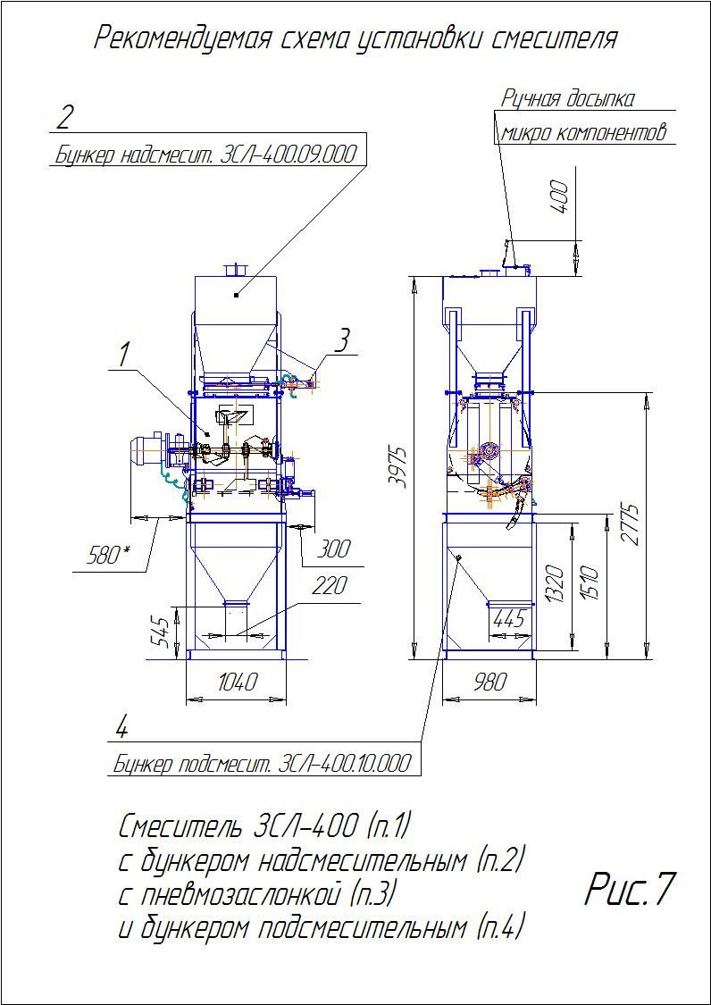 Рекомендована схема встановлення ЗСЛ-400