Змішувач горизонтальний протитечійний періодичної дії марки ЗМГ-2000 призначений для змішування компонентів комбікормів, після порційного дозування.
Змішувач може бути застосований на комбікормових заводах та в цехах з виробництва збагачувальних сумішей.
|
НАЙМЕНУВАННЯ ПАРАМЕТРА
|
ЗНАЧЕННЯ |
|
Продуктивність технічна до, т/год |
6 |
|
Об'єм, м.куб. |
2,4 |
|
Ступінь однорідності змішування до, % |
95 |
|
Цикл змішування, хв |
4-5 |
Призначення виробу
Змішувач горизонтальний протитечійний періодичної дії марки ЗМГ-2000 призначений для змішування компонентів комбікормів після порційного дозування. Змішувач може бути застосований на комбікормових заводах і в цехах по виробництву збагачувальних сумішей.
Основні параметри ЗМГ-2000
|
НАЙМЕНУВАННЯ ПАРАМЕТРА
|
ЗНАЧЕННЯ |
|
Продуктивність технічна до, т/год |
6 |
|
Об'єм, м.куб. |
2,4 |
|
Ступінь однорідності змішування до, % |
95 |
|
Цикл змішування, хв |
4-5 |
| Час завантаження, сек |
7-15 |
|
Час вивантаження, хв |
1,5-3 |
| Частота обертання ротора, об/хв |
28 |
|
Встановлена потужність: ротора змішувача, кВт |
11 |
|
Встановлена потужність: шнека вивантаження, кВт |
1,5 |
| Встановлена потужність: електрозаслонки вивантаження змішувача, кВт |
0,12 |
| Встановлена потужність: заслонки надзмішувального бункера, кВт |
0,12 |
|
Габаритні розміри, мм: - довжина - ширина - висота з надзмішувальним бункером (без надзмішувального бункера) |
3500
|
|
Вага, кг |
2400 (2000) |
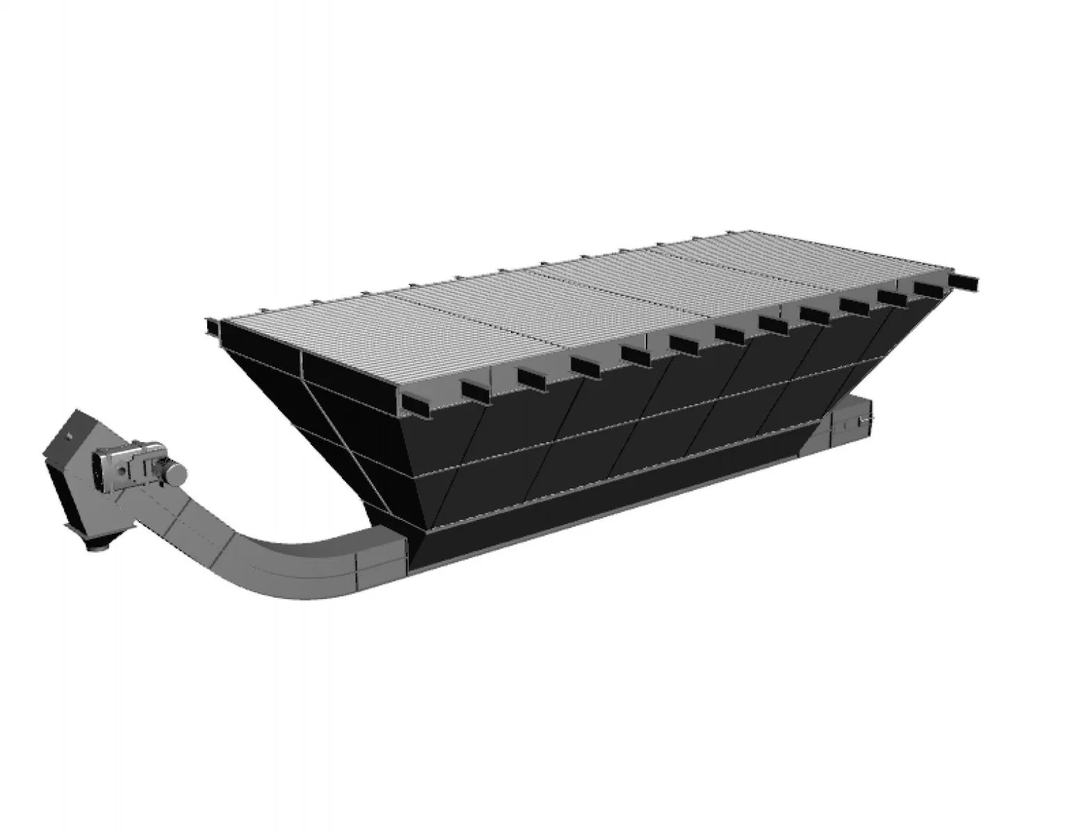
Пристрій і робота
Змішувач складається з
-корпуса,
-ротора,
-привода,
-рами,
-електро-(пневмо-)заслінки вивантаження змішувача,
-шнека вивантаження,
-** бункера надзмішувального,
-** електро-(пневмо-)заслінки вивантаження бункера надзмішувального.
(**за замовленням споживача).
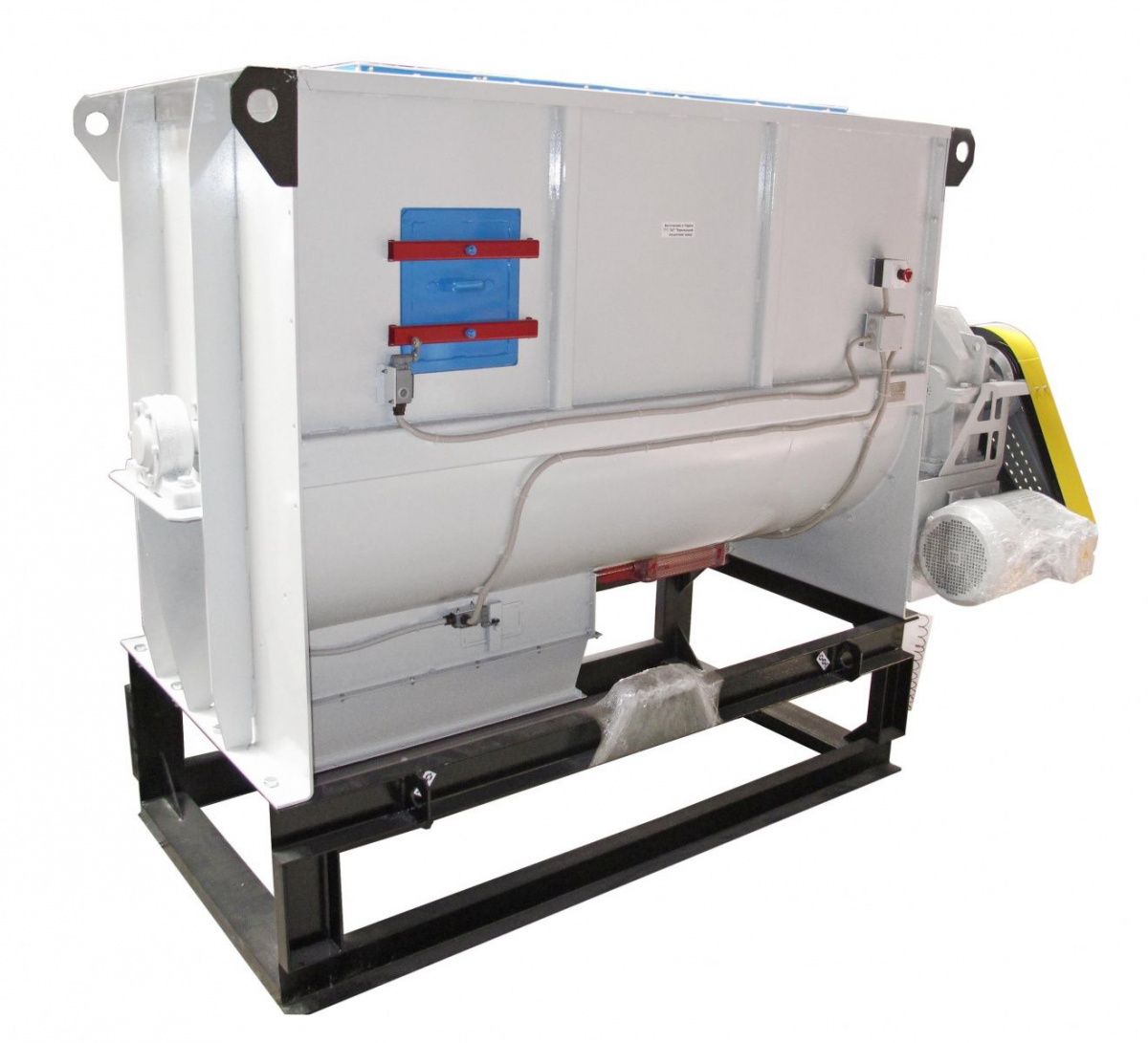
Корпус змішувача ЗМГ-2000 являє собою сталеву зварену конструкцію, напівциліндричної форми. У бічних стінках корпусу змішувача є вікна, закриті кришками, зблоковані з електродвигуном кінцевими вимикачами і призначеними для виробництва ремонтних робіт, візуального контролю і періодичної очистки змішувача зсередини скребковим та пневматичним інструментом.
КАТЕГОРИЧНО ЗАБОРОНЯЄТЬСЯ відключати кінцеві вимикачі на кришках при роботі і технічному обслуговуванні змішувача, а також продовжувати експлуатацію змішувача при їх несправності.
Роз'ємна конструкція корпусу дозволяє провести демонтаж ротора. Ротор являє собою вал, на якому розташовані 4 лопаті-спіралі 2-внутрішні і 2 - зовнішні з протилежною навивкою. Вал ротора спирається на підшипники, які встановлені на торцових стінках корпусу змішувача.
Привід забезпечує задану частоту обертання ротора від електродвигуна через клинопасову передачу і редуктор.
Рама представляє собою зварну конструкцію для установки змішувача на фундаменти. Заслінка вивантаження змішувача. Розвантаження комбікормової суміші здійснюється через вікна в нижній частині корпусу, які в процесі змішування перекриті заслінкою. Заслінка являє собою лист, вигнутий по радіусу корпусу змішувача. Робота заслінки здійснюється електро - або пневмо-приводом. Величина відкриття заслінки при потребі регулюється кінцевими вимикачами. Шнек вивантаження-6 призначений для вивантаження комбікормової суміші з-під змішувача і транспортування уздовж змішувача на відстань 1-1,5 м для подачі в наступний механізм (норію, шнек).
Принцип роботи змішувача ЗМГ-2000: дозовані компоненти, що поступають у надзмішувальний бункер, накопичуються до досягнення порції. Потім дуже швидко за 8-12 секунд відбувається вивантаження в корпус змішувача, (короткий час завантаження запобігає ефекту розшаровування компонентів), в корпусі змішувача компоненти при обертанні шнекового ротора піддаються інтенсивному зустрічному перемішуванню внутрішніми і зовнішніми лопатями-спіралями. При закінченні часу змішування, відкривається заслінка і отримана суміш направляється зовнішніми шнеками до місця вивантаження з корпусу, а потім шнеком вивантажується із змішувача.
 Нормаль ЗМГ-2000