Фільтри автономні локальні з автономним очищенням (імпульсною продувкою) марки АФ призначені для очищення повітря від пилу. Підходять як для розширення існуючих центральних аспіраційних установок, так і для самостійної установки на комплексному обладнанні, заснованому на точкових фільтрах.
Установи фільтри локальні - запобіжи подіям надзвичайним!
|
НАЙМЕНУВАННЯ ПАРАМЕТРА |
ОД. |
АФ-3.KS-200 |
АФ-3.Н-20 |
АФ-6.KS-320 |
АФ-6.Н-50 |
|
Тип фільтра |
- |
локальный з автономним очищенням |
|||
|
Продуктивність по повітрю, min |
м3/год |
900 |
1800 |
||
|
Відносна вологість повітря, не больше |
% |
75 |
|||
Призначення виробу
Фільтри автономні локальні з автономним очищенням (імпульсною продувкою) АФ призначені для очищення повітря від пилу. Підходять як для розширення існуючих центральних аспіраційних установок, так і для самостійної установки на комплексному обладнанні, заснованому на точкових фільтрах.
Порівняння основних параметрів АФ
|
НАЙМЕНУВАННЯ ПАРАМЕТРА |
ОД. |
АФ-3.KS-200 |
АФ-3.Н-20 |
АФ-6.KS-320 |
АФ-6.Н-50 |
|
Тип фільтра |
- |
локальный з автономним очищенням |
|||
|
Продуктивність по повітрю, min |
м3/год |
900 |
1800 |
||
|
Відносна вологість повітря, не больше |
% |
75 |
|||
|
Площа фільтрувальної поверхні |
м2 |
3 |
6 |
||
|
Кількість фільтрувальних елементів |
шт. |
2 |
4 |
||
|
Вага |
Кг |
200 |
210 |
250 |
260 |
|
Витрати стисненого повітря, min |
л/хв |
65 |
130 |
||
|
Встановлена потужність |
кВт |
0,75 |
2,2 |
||
|
Тиск стисненого повітря, не менше |
бар |
6…6,2 |
|||
|
Вхідна концентрація пилу |
г/м3 |
до 50 |
|||
|
Залишкова концентрація пилу |
г/м3 |
до 4 |
|||
|
Опір фільтра ΔР |
кПа |
1,1…1,2 |
|||
|
Тривалість струшування |
с |
0,1…0,2 |
|||
|
Періодичність струшування пари елементів |
хв |
2…4 |
|||
Якщо для подачі стисненого повітря на установку передбачений окремий компресор, то система повітроводів повинна бути не менше 10 м завдовжки, щоб виконувати функції охолодження.
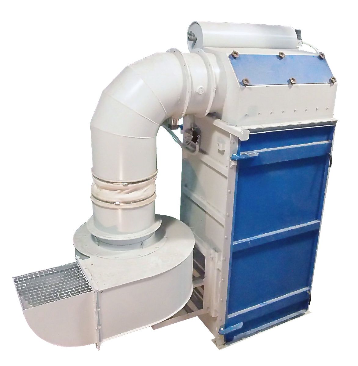
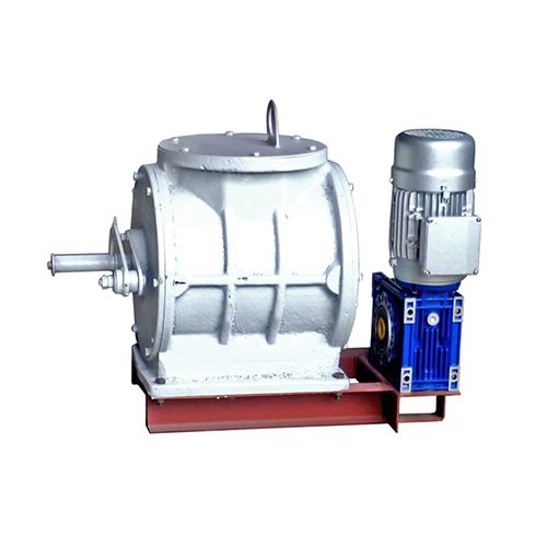
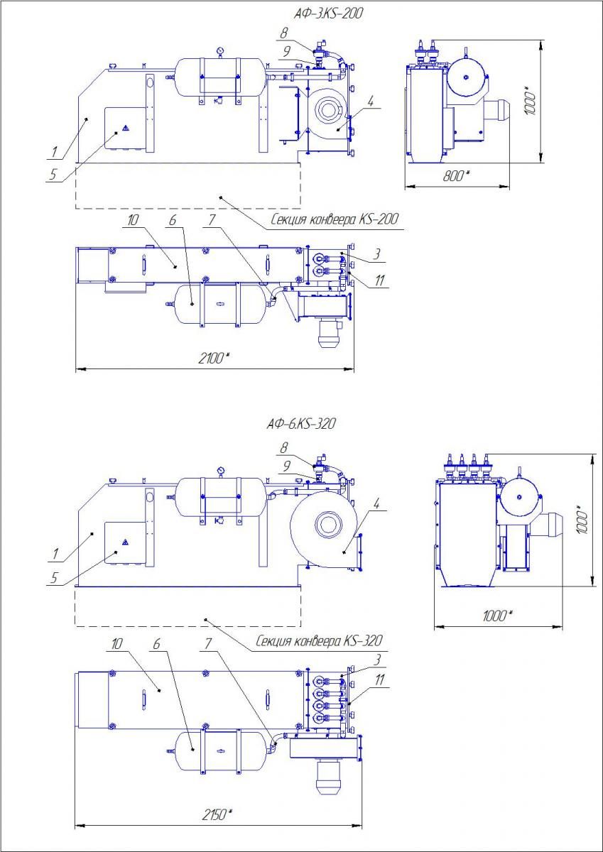
Пристрій і робота
Забруднене повітря надходить в камеру фільтрів, що містить фільтруючі елементи, де пил осідає на їх зовнішній поверхні по мірі проходження повітря крізь матеріал фільтра. При цьому він (пил) створює також важливий для процесу фільтрації так званий додатковий фільтруючий шар. Очищене повітря надходить з кожного елемента у верхню камеру, а звідти через витяжний вентилятор виходить в атмосферу. Через певні проміжки часу, запрограмовані в контролері модуля очищення, кожен елемент отримує по черзі короткочасне впорскування стисненого повітря з ресивера через колектор, клапан і відповідну інжекторну трубку, яка має ряд отворів невеликого діаметра, розташованих навпроти випускних отворів елементів. Діаметр цих отворів і відстань від них до елемента розраховані оптимальним чином, забезпечуючи примусове втягування значного обсягу навколишнього повітря всередину разом з кожним впорскуванням стисненого повітря. Це призводить до короткочасної потужної зміни напрямку потоку повітря через матеріал фільтра, роздуваючи пакет і ефективно струшуючи з нього шар пилу, який повертається назад в потік продуктів.
Тривалість циклів вибирається таким чином, щоб забезпечити ефективну фільтрацію, запобігти залипання продуктом простір між картриджами і підтримувати опір фільтра у допустимих межах.
На установці передбачені кришки для забезпечення доступу до фільтрувальних елементів з метою їх заміни або ручного очищення.
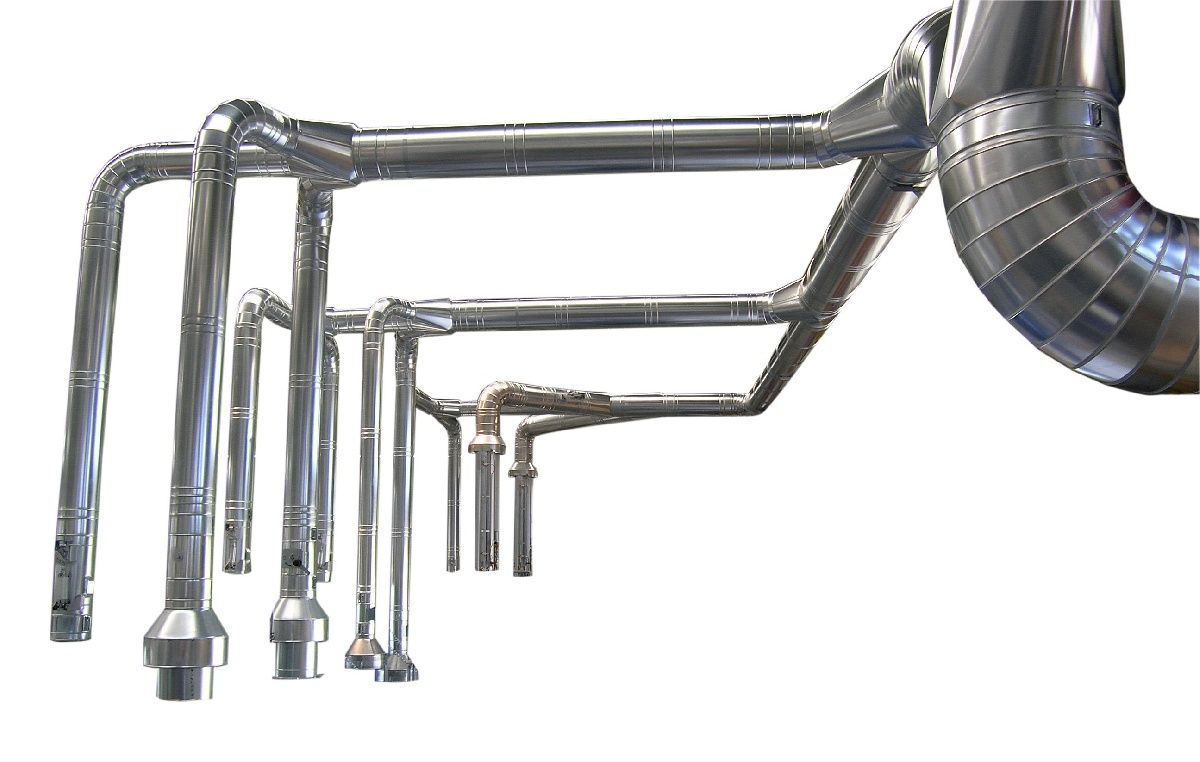
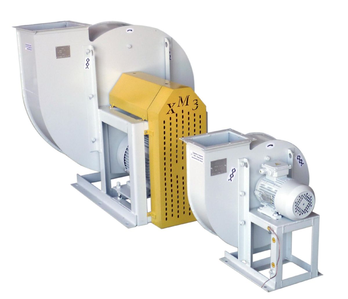
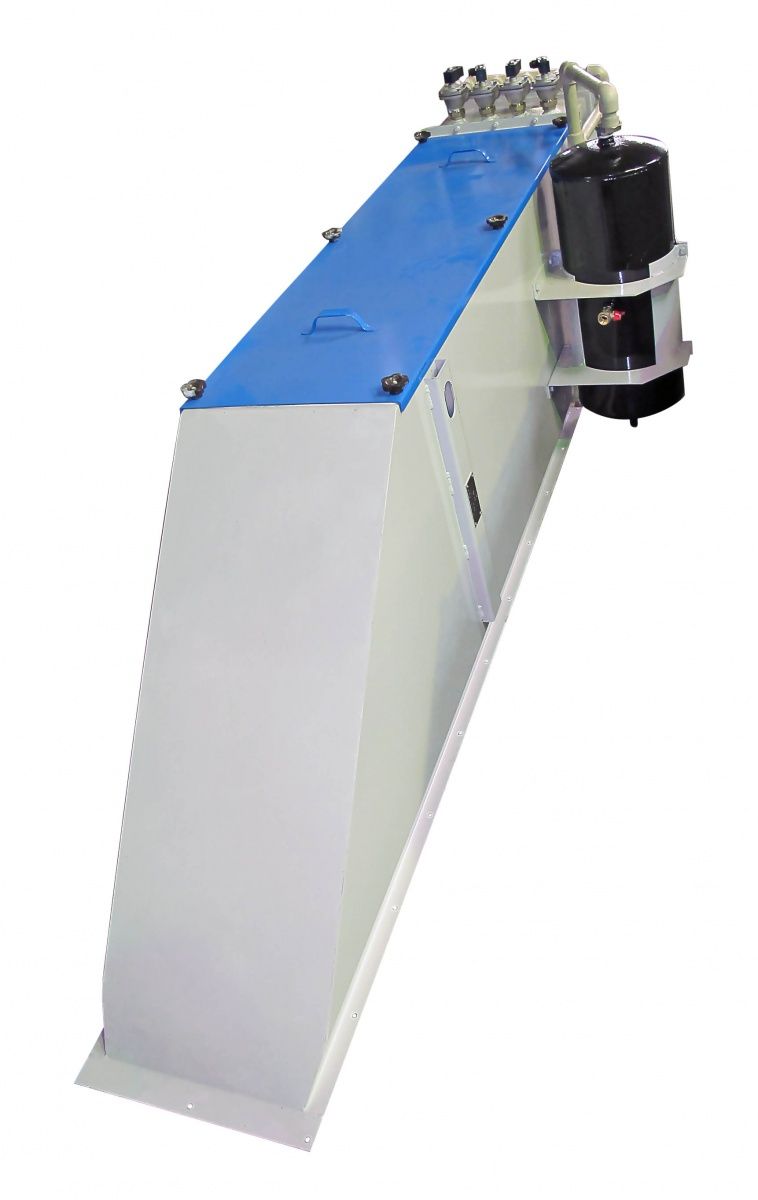
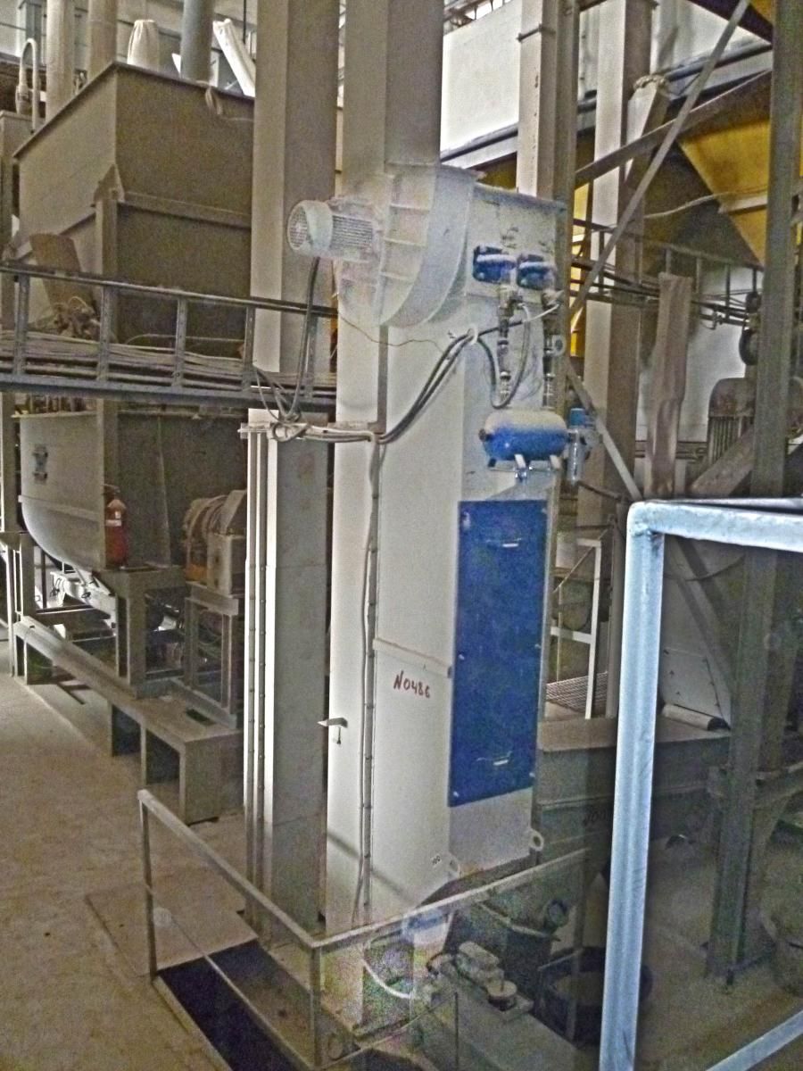 АФ в роботі
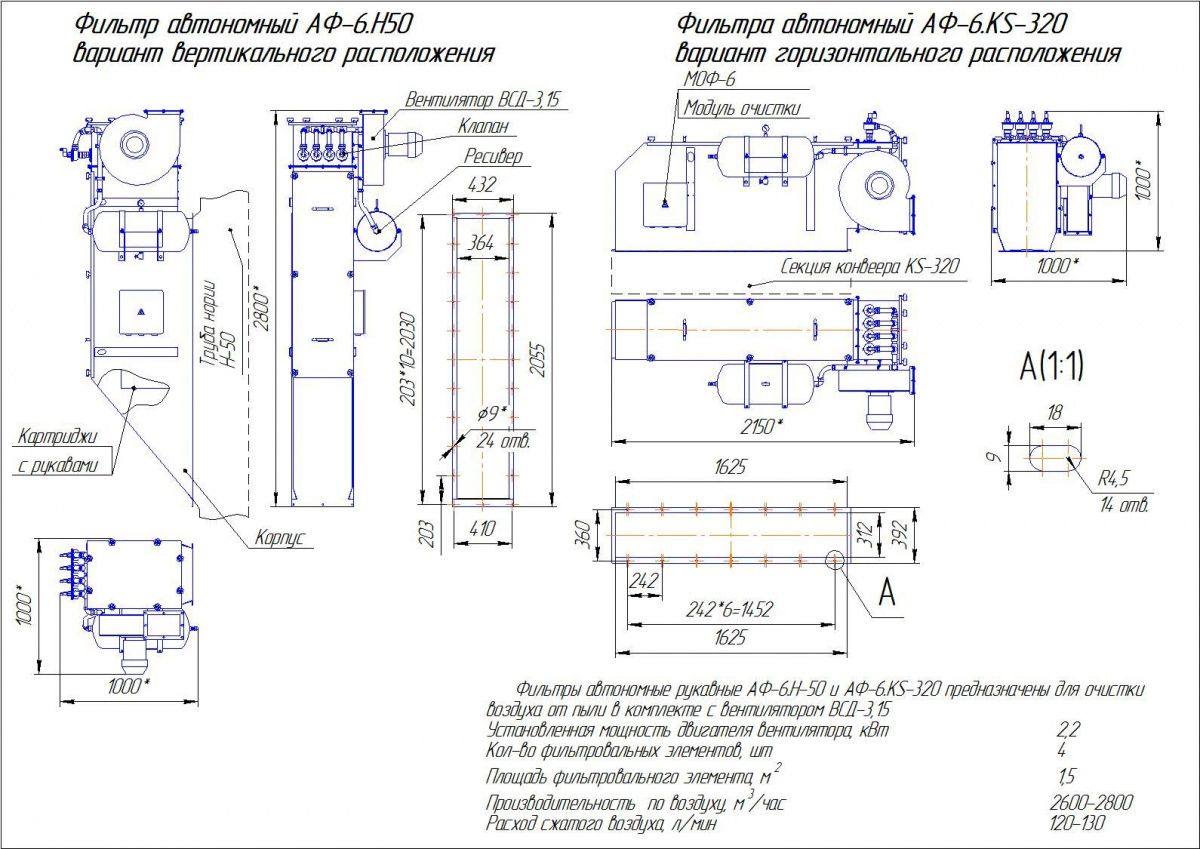
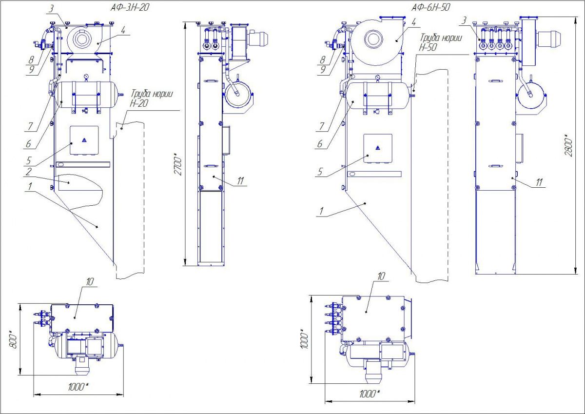 Габаритне креслення
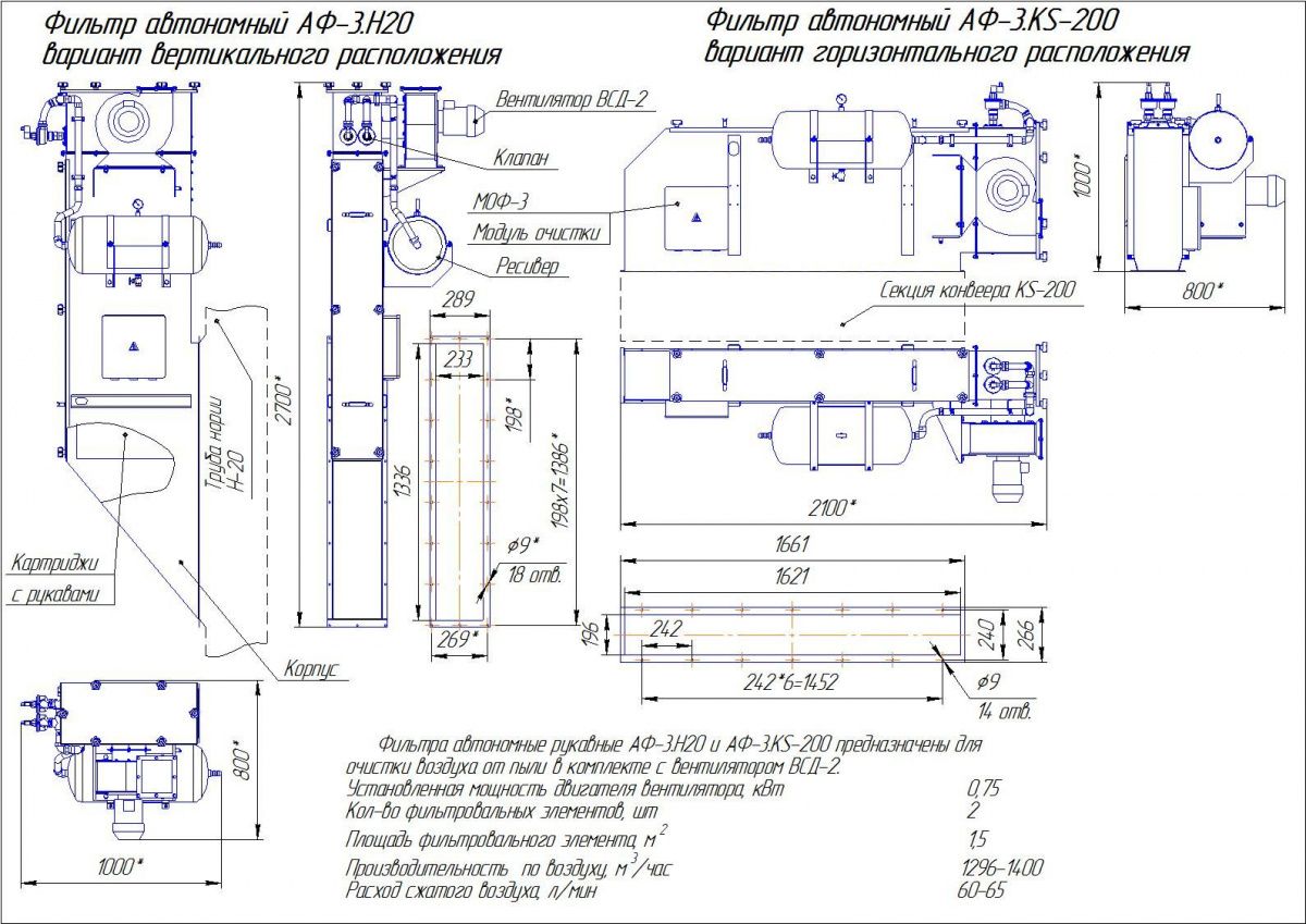 Нормаль
 Нормаль
 Габаритні розміри
 АФ в роботі