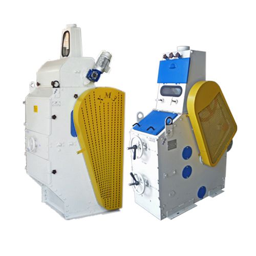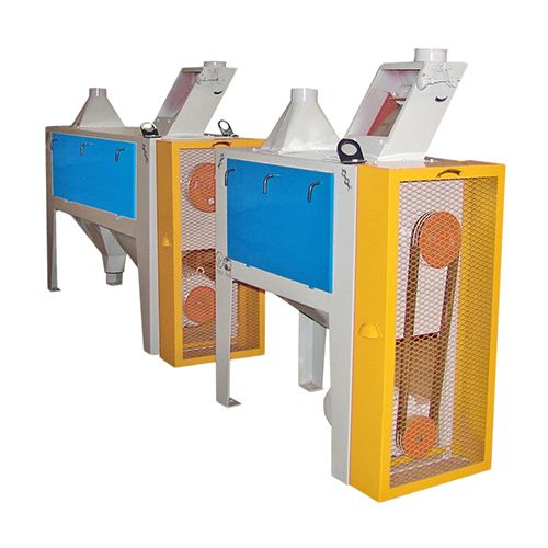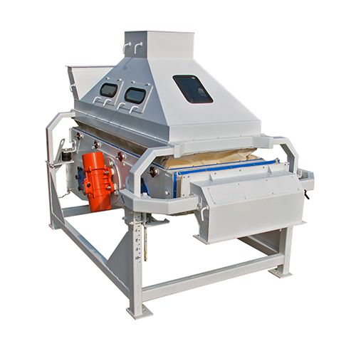
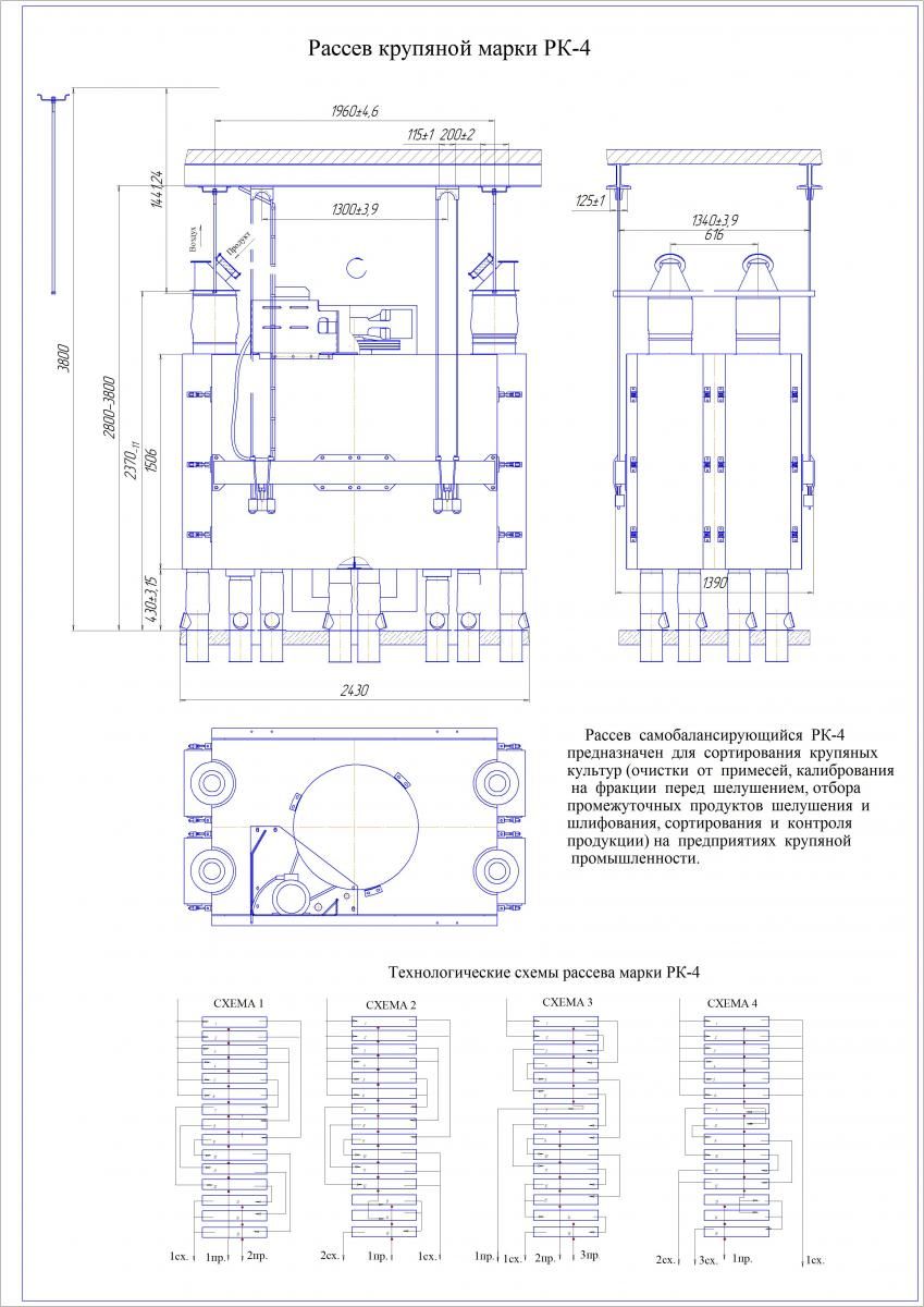
Розсів самобалансуючий РК-2 і РК-4 призначений для сортування круп'яних культур (очищення від домішок, калібрування на фракції перед лущенням, відбору проміжних продуктів лущення і шліфування, сортування і контролю продукції) на підприємствах круп'яної промисловості.
|
НАЙМЕНУВАННЯ ПАРАМЕТРА
|
РК-4 |
|
Число секцій (прийомів) |
4 |
|
Номінальний розмір ситових рамок, мм |
400*800 |
|
Загальна номінальна корисна площа сит, м2 |
13,5 |
|
НАЙМЕНУВАННЯ ПАРАМЕТРА
|
РК-2 |
|
Число секцій (прийомів) |
2 |
|
Номінальний розмір ситових рамок, мм |
400*800 |
|
Загальна номінальна корисна площа сит, м2 |
6,75 |
Призначення виробу
Розсів самобалансуючий РК-2 і РК-4 (далі розсів) призначений для сортування круп'яних культур (очищення від домішок, калібрування на фракції перед лущенням, відбору проміжних продуктів лущення і шліфування, сортування і контролю продукції) на підприємствах круп'яної промисловості.
Продуктивність РК-4
|
Найменування культури |
Технологічна операція |
Технічна продуктивність, т/год |
|
Гречка
Овес Просо Рис
Ячмінь |
Сортування 1 і 2 фракції перед лущенням
Сортування продуктів лущення: 1 фракції 2 фракції Контроль крупи Контроль пшона Поділ продуктів лущення Поділ продуктів шліфування Контроль мучки Попереднє сортування крупиСортування 1-го номера крупи Контроль мучки |
8
12 16 5,2 8 16 16 6,8 16 7 1,6 |
Основні параметри РК-4
|
НАЙМЕНУВАННЯ ПАРАМЕТРА |
ЗНАЧЕННЯ |
|
Число секцій (прийомів) |
4 |
|
Номінальний розмір ситових рамок, мм |
400*800 |
|
Загальна номінальна корисна площа сит, м2 |
13,5 |
|
Частота кругових коливань корпусу, с-1 (коливань в хвилину), з відхиленням не більше 0,17 с-1 (10 коливань в хвилину) |
3,0; 3,2; 3,7; 3,8; (180; 190; 220; 230) |
|
Радіус кругових коливань корпусу, мм |
28-22 |
|
Витрата повітря на аспірацію, м3/год |
840-1080 |
|
Аеродинамічний опір, Па (мм вод. ст.) |
150-200 (15-20) |
|
Потужність електродвигуна, кВт |
3,0 |
|
Габаритні розміри, мм, не більше -довжина -ширина -висота до приймальної дошки |
2310 1390 2370 |
|
Маса, кг не більше |
2415 |
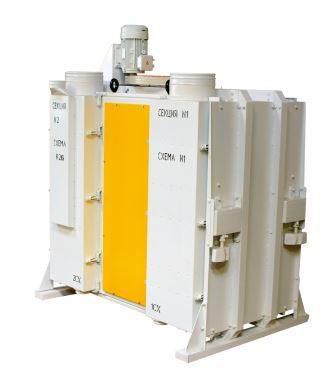
Розсів виготовляється у десяти варіантах, що відрізняються функціональними схемами секцій, розташування яких наведено у розділі "ФОТО"
Продуктивність РК-2
|
Найменування культури |
Технологічна операція |
Технічна продуктивність, т/год |
|
Гречка
Овес Просо Рис
Ячмінь |
Сортування 1 і 2 фракції перед лущенням Сортування продуктів лущення: 1 фракції2 фракції Контроль крупи Контроль пшона Поділ продуктів лущення Поділ продуктів шліфування Контроль мучки Попереднє сортування крупи
Сортування 1-го номера крупи Контроль мучки |
4
6 8 2,6 4 8 8 3,4 8 3,5 0,8 |
Основні параметри РК-2
НАЙМЕНУВАННЯ ПАРАМЕТРА | ЗНАЧЕННЯ |
Число секцій (прийомів) | 2 |
Номінальний розмір ситових рамок, мм | 400*800 |
Загальна номінальна корисна площа сит, м2 | 6,75 |
Частота кругових коливань корпусу, с-1 (коливань в хвилину), з відхиленням не більше 0,17 с-1 (10 коливань в хвилину) | 3,0; 3,2; 3,7; 3,8; (180; 190; 220; 230) |
Радіус кругових коливань корпусу, мм | 28-22 |
Витрата повітря на аспірацію, м3/год | 840-1080 |
Аеродинамічний опір, Па (мм вод. ст.) | 150-200 (15-20) |
Потужність електродвигуна, кВт | 3,0 |
Габаритні розміри, мм, не більше -довжина -ширина -висота до приймальної дошки | 2310 1390 2370 |
Маса, кг не більше | 2415 |
Пристрій і робота
Розсів являє собою розбірну конструкцію шафового типу з висувними ситовими рамками і складається з ситового кузова, несучої рами, балансирного механізму і привода. На сталевих канатах розсів підвішується до підвісок, прикріплених до стельової рами. Кузов розділений перегородками несучої рами на чотири секції. В направляючих секції встановлено по п'ятнадцять ситових рамок з піддонами, збірником. Зовнішні обшивки кузова і направляючі секцій утворюють бічні перепускні канали. Двері секцій мають подвійні стінки, утворюють перепускні канали з боку прийому. З боку протилежної прийому, перепускні канали секцій виконані у вигляді знімних розподільних коробок, прикріплених до задніх стійок секцій. Очищення сит здійснюється гумовими кульками. На кузові встановлено приймальні патрубки (живильники) з направляючими, що дозволяють рівномірно розподіляти вихідний продукт на приймальні ситові рамки кожної секції. До патрубків і до патрубків приймальних пристроїв кріпляться приймальні рукава. До патрубків закріпленим до днища кузова і до підлогових патрубків кріпляться випускні рукава. До приймальних пристроїв, підвішеним до стельової рами за допомогою державок і штанг, кріпляться приймальні коробки. До останніх кріпляться повітроводи, системи аспірації і самопливи подачі продукту. Несуча рама являє собою суцільно механічну зварну конструкцію. До несучої рами кріпляться секції, бічна обшивка, підлога і дах кузова, а також на ній вбудовані верхній і нижній підшипникові вузли балансирного механізму, за допомогою якого розсів приводиться в рух. Ситова рамка виготовляється з дерев'яних брусків. Рамка розділена брусками на 4 комірки. В комірку рамки встановлюються вкладиші, що представляють собою коробку, дно якої виконано на зразок решітного полотна. Боковини коробки не мають отворів і служать для захисту дерев'яних частин рамки від зносу їх очисниками. Очисники, кульки Ø 25 мм, призначені для очищення сит, вкладаються по 2шт. перед набиванням сит на круп'яних підприємствах. Ситові рамки можуть бути виконані в двох виконаннях: односхилі і двосхилі. У односхилих рамках прохід сит випускається тільки в одну сторону (в один бічний канал); в двосхилих - в обидві сторони. Піддон являє собою лист з загнутими кінцями по короткій стороні і прикріпленими знизу двома куточками, що служить для фіксації піддону в секції ситового кузова, для виїмки піддону з рамкою з секції, а також для надання йому необхідної жорсткості. Для запобігання змішування різних фракцій продукту, а також для більш вільного переміщення по направляючих рамок секцій на поздовжніх брусках ситової рамки приклеєні прокладки з ворсової тканини. Між рамкою і піддоном, а також на середніх брусках приклеєні байкові прокладки. Механізм дозволяє регулювати радіус кругових коливань розсіву шляхом зміни маси балансира за рахунок установки або знімання змінних вантажів. Число оборотів балансирного механізму регулюється змінними шківами на електродвигуні приводу розсіву. Привід кузова розсіву здійснюється від електродвигуна клиноремінною передачею. Двигун приводу встановлюється на кронштейні, закріпленому на шафі. Натяг ременів здійснюється переміщенням двигуна по пазах плити з допомогою натяжних болтів.
Кінематична схема розсіву показана в розділі "ФОТО". Підлогові патрубки служать для прийому з кузова розсіву розділених фракцій продукту. Верхні патрубки з'єднуються тканевими рукавами з патрубками кузова, внизу вони мають відбортовку для приєднання до них самопливів з допомогою стандартних хомутів. Для відбору проб на верхньому патрубку є отвір, що закривається заглушкою. Основою патрубків служить коробка, яка після монтажу розсіву заливається бетоном. Отвори, наявні на бортах коробки, призначені для зручності установки патрубків при монтажі. Привід розсіву здійснюється від двигуна АІР112МА6УЗ (потужність 3 кВт, частота обертання: 950 об/хв). Живлення електродвигуна має здійснюватися від трифазної мережі змінного струму частотою 50±1 Гц, напругою 380В. Рекомендована схема електрична розсіву передбачає ввімкнення і вимкнення двигуна, захист двигуна і електропроводки від струмів короткого замикання, від перевантаження, від мінімальної напруги. При натисканні кнопки S В. 2 посту спрацьовує і само блокується магнітний пускач КМ, який своїми контактами підключає двигун до силової мережі. Зупинка двигуна здійснюється натисканням кнопки S В. 1. Принцип роботи розсіву полягає в паралельному та послідовному просіюванні продукту через набір плоских горизонтальних сит, що здійснюють круговий поступальний рух. При надходженні продукту через приймальні коробки і приймальні патрубки на сита починається процес сортування.
Рух продукту всередині шафи здійснюється залежно від виконання розсіву за однією з технологічних схем.
Під час роботи розсіву під навантаженням особливу увагу слід звертати на:
-рівномірне завантаження всіх секцій;
-герметичність кузова, не допускаючи послаблення різьбових з'єднань і пилення продуктів;
-відсутність підсівання однієї кінцевої фракції в іншу;
-стан всіх рухомих вузлів і деталей, безшумність роботи;
-очищення сит;
-ефективність аспірації, не допускаючи запотівання стінок усередині кузова при температурі навколишнього середовища нижче 15ºС.
Ефективність процесу сепарування і коефіцієнт вилучення проходової фракції залежать від властивості вихідного продукту, навантаження і можуть регулюватися зміною кінематичних параметрів розсіву – частоти і амплітуди коливань. Встановлення оптимального кінематичного режиму розсіву повинно мати на меті одержання найкращого технологічного ефекту. В залежності від вихідного продукту і системи технологічного процесу в таблиці нижче наводяться оптимальні кінематичні параметри розсіву. Амплітуда кругових коливань розсіву регулюється з допомогою змінних вантажів, закріплених на балансирі. У таблиці представлена залежність радіуса (1/2 амплітуди) коливань розсіву під навантаженням від маси змінних вантажів. В залежності від необхідного радіуса визначається кількість додаткових вантажів, які необхідно закріпити на балансирах.
|
Культура |
Найменування технологічного процесу |
Кінемати- чні параметри |
№ схеми |
Найменування продукту | |||||||
|
прохід |
схід |
||||||||||
|
1 |
2 |
3 |
1 |
2 |
3 |
||||||
|
R.,мм |
n,об/хв. |
||||||||||
|
1 |
2 |
3 |
4 |
5 |
6 |
7 |
8 |
9 |
10 |
11 |
|
|
Рис |
Поділ продуктів лущення
|
25 |
190 |
4 |
мучка |
|
|
суміш ядра і зерна |
суміш ядра і зерна |
ядро |
|
|
Поділ продуктів шліфування
|
25 |
230 |
4 |
дробле- нка |
|
|
крупа |
крупа |
суміш крупи і дробленки |
||
|
Контроль мучки |
25 |
230 |
3 |
мучка |
мучка |
дробле- нка |
крупа |
|
|
|
|
|
Просо |
Очищення від великих і малих домішок |
26 |
220 |
1 |
дрібні домішки |
очищене зерно |
|
великі домішки |
|
|
|
|
Сортування по крупності |
26 |
180 |
1 |
дрібне зерно |
дрібне зерно |
|
велике зерно |
|
|
||
|
Контроль пшона |
26 |
190 |
3 |
дробленка і мучка |
дробленка і мучка |
пшоно |
великі домішки |
|
|
|
|
|
Ячмінь |
Сортування пенсака |
25 |
190 |
2 |
мучка |
|
|
|
ціле зерно |
дроблене зерно |
|
|
Сортування продуктів дроблення |
25 |
190 |
4 |
мучка |
|
|
зерно |
велика крупа |
дрібна крупа |
||
|
Сортування ячневої крупи |
25 |
190 |
4 |
мучка |
|
|
зерно |
велика крупа |
дрібна крупа |
||
|
Сортування перлової крупи (попереднє) |
25 |
190 |
1 |
мучка |
|
|
полірування |
крупа №1 |
суміш номерів, крім №1 |
||
|
Сортування крупи по номерам: 1,2,3 |
25 |
190 |
2 |
дрібна крупа |
дрібна крупа |
|
готова крупа |
|
|
||
|
4,5 |
25 |
220 |
3 |
мучка |
дрібна крупа |
|
готова крупа |
|
|
||
|
Контроль мучки |
25 |
230 |
3 |
мучка |
мучка |
дрібна крупа |
крупна крупа |
|
|
|
|
|
Овес |
Контроль крупи |
25 |
190 |
3 |
дроблена крупа і мучка |
дроблена крупа і мучка |
крупа |
крупні домішки |
|
|
|
|
Гречка |
Сортування фракції перед лущенням |
23 |
190 |
1 |
дрібне зерно |
|
основна фракція |
важковідокремлювані домішки |
|
|
|
|
Поділ продуктів лущення |
26 |
190 |
2 |
проділ |
|
|
другак |
ядро |
|
||
|
Контроль ядриці |
26 |
190 |
2а |
проділ |
|
|
важковідокремлювані домішки |
крупа |
|
||
|
Контроль проділу |
26 |
220 |
3 |
мучка |
дрібний проділ |
великий проділ |
крупа |
|
|
||
|
Контроль лузги |
26 |
220 |
4 |
мучка |
|
|
лузга |
лузга |
проділ |
|
|
|
Варіанти набору грузів |
Позиція додаткового груза на рис.2.2.9 |
Маса одного груза, кг |
Загальна кількість додаткових грузів |
Маса всіх додаткових грузів, кг |
Загальна маса балансирних грузів, кг |
Радіус коливань корпуса, мм |
|
1 |
1 |
2,3 |
8 |
18,4 |
236 |
22,6 |
|
2 |
1 |
2,3 |
8 |
38,4 |
256 |
25,1 |
|
2 |
2 |
2,5 |
8 |
38,4 |
256 |
25,1 |
|
3 |
1 |
2,3 |
8 |
48,4 |
266 |
26,3 |
|
" |
2 |
2,5 |
8 |
48,4 |
266 |
26,3 |
|
" |
3 |
1,28 |
8 |
48,4 |
266 |
26,3 |
|
IV |
1 |
2,3 |
8 |
68,4 |
286 |
28,0 |
|
" |
2 |
2,5 |
8 |
68,4 |
286 |
28,0 |
|
" |
3 |
1,28 |
8 |
68,4 |
286 |
28,0 |
|
" |
4 |
4,9 |
4 |
68,4 |
286 |
28,0 |
При встановленні додаткових вантажів необхідно стежити, щоб маса і розташування їх на верхньому і нижньому балансирах були однакові. У разі невиконання цієї умови несприятливо розподіляються сили в підшипникових вузлах, порушується горизонтальність руху кузова і ситових рамок, погіршується ефект сепарування продуктів. Необхідну частоту коливань розсіву встановлюють підбором змінного шківа електродвигуна згідно з даними, зазначеними в таблиці.
|
Частота коливань |
Діаметр шківа, мм |
|
|
Розрахунковий |
Зовнішній |
|
|
180 190 220 230 |
120 126 145 152 |
128,4 134,4 153,4 160 |
Радіус коливань корпусу розсіва вимірюють наступним чином. На вільну площадку даху розсіву приклеюють по куточкам чистий аркуш паперу. Потім торкаються листа відточеним олівцем, нерухомо закріпленим у спеціальному утримувачі або тримаючи його нерухомо у витягнутій руці. Олівець залишає на папері слід - траєкторію коливання розсіву, близьку до кола. Вимірюють найбільше Д1 і найменше Д2 відстань між двома протилежними точками кола і визначають середній радіус R сер. за формулою:
R сер. =( Д1 +Д2)/4
У разі необхідності переобладнання якої-небудь однієї або декількох секцій, з однієї функціональної схеми в іншу, споживач розсіву може за окремим замовленням отримати необхідні комплекти змінних частин і своїми силами і засобами переробити розсів на потрібне йому виконання.
Призначення групових комплектів змінних частин:
Комплект №1 -для переведення секції схеми 1 на схему 2;
Комплект №2 -для переведення секції схеми 1 на схему 3;
Комплект №3 -для переведення секції схеми 2 на схему 1;
Комплект №4 -для переведення секції схеми 2 на схему 3;
Комплект №5 -для переведення секції схеми 3 на схему 1;
Комплект №6 -для переведення секції схеми 3 на схему 2;
Кожен комплект містить набір змінних частин на одну секцію розсіву. Відомість групових комплектів змінних частин наведена в додатку.
Переналагодження секцій розсіву з однієї функціональної схеми в іншу рекомендується проводити в наступній послідовності:
- зняти відповідні перепускні коробки або листи з вікнами в двері та секції шафи, відвернути кріпильні гайки і на їх місце поставити певні коробки і листи з вікнами з комплекту змінних частин. При заміні коробок і листів необхідно ретельно перевірити відсутність щілин на стиках сусідніх елементів;
- наклеїти ущільнення Клеєм 88-НП ТУ 38-105.540.
- відкрутити гайки і зняти підлягаючі заміні направляючі, демонтувати або встановити знову перекривки;
- для зміни напряму руху проходових фракцій з односхилих піддонів ситових рамок необхідно вийняти піддон з рамкою і повернути його на 180˚.
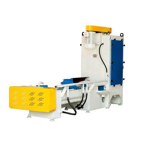
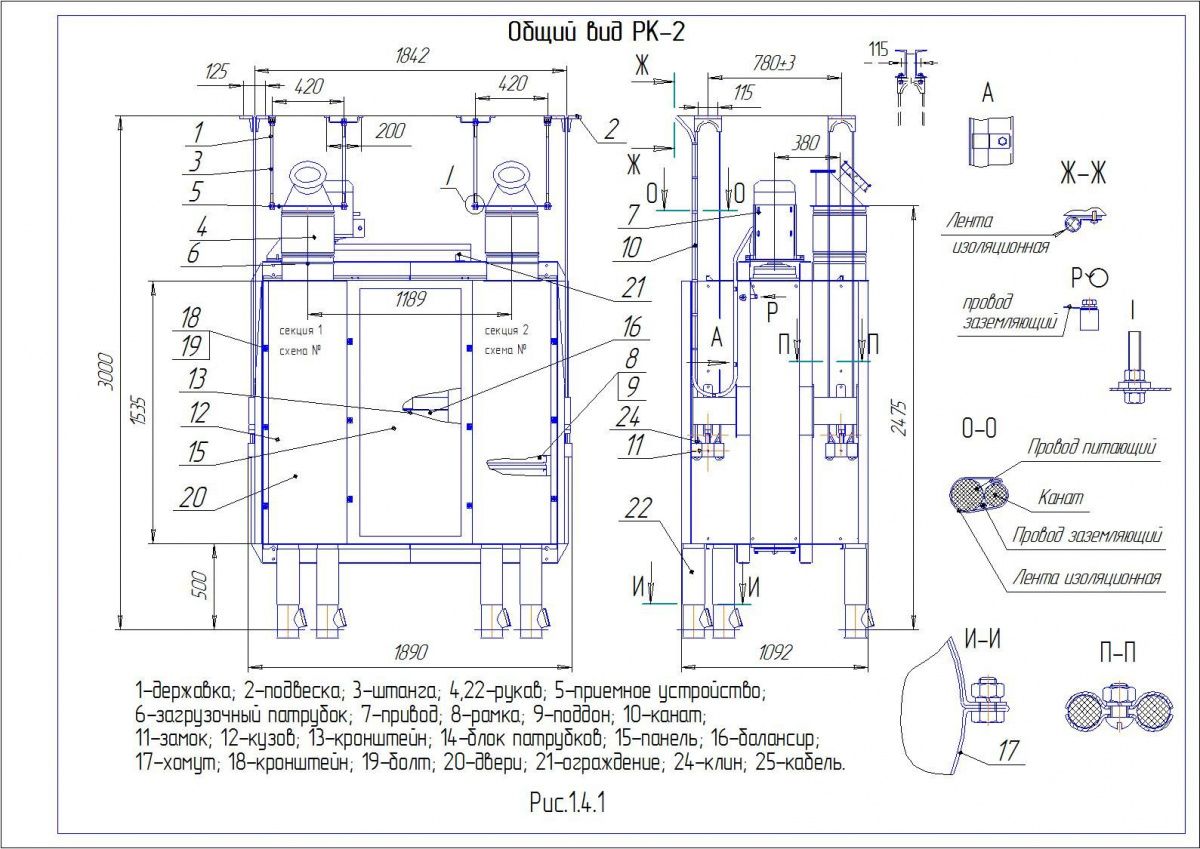 Загальий вид РК-2
 Нормаль РК-4
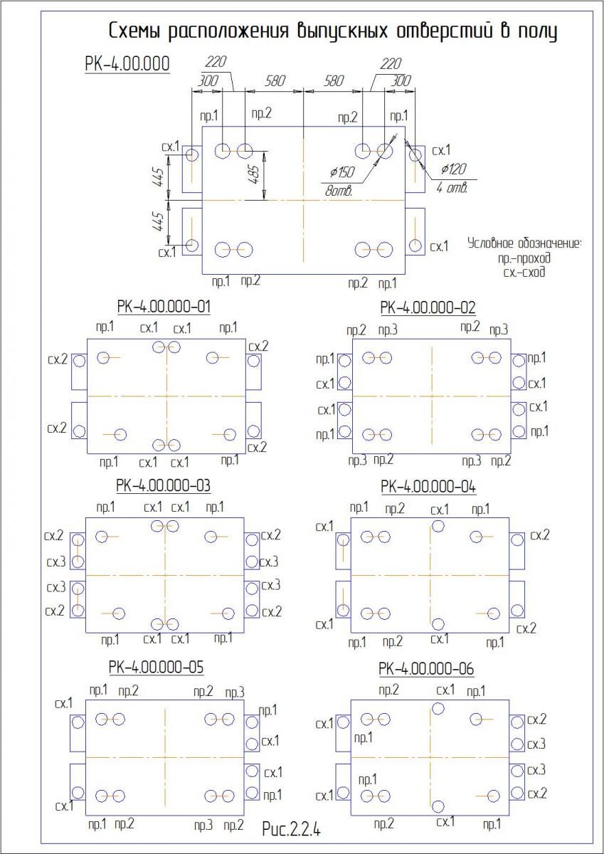 Схема розташування випускних отворів РК-4
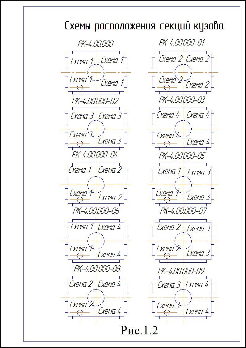 Схема розміщення секцій кузова РК-4
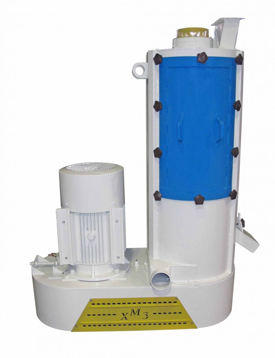
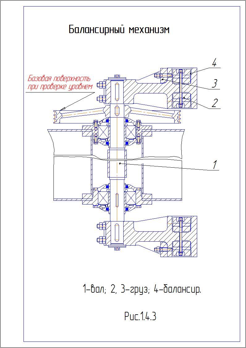 Балансирний механізм
 Варіанти змінних грузів
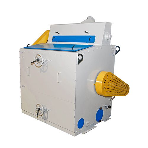
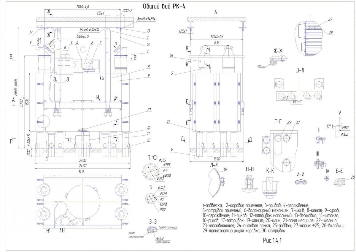 Загальий вид РК-4
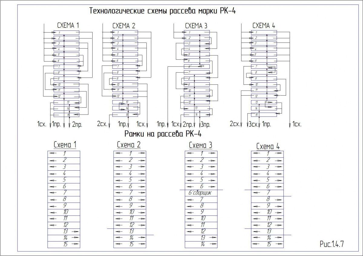 Технологічні схеми розсіву РК-4
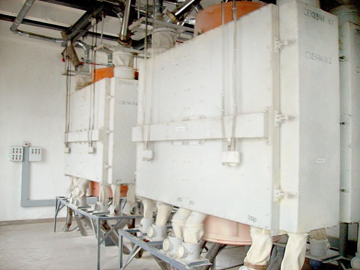 РК-4 в роботі